

Table of Contents
Helical pile installation is one of the most efficient deep foundation construction methods available for new construction, remedial support, underpinning, transmission structures, solar foundations, boardwalks, and industrial projects. Unlike driven piles that rely on impact energy or drilled foundations that require soil removal, helical piles are advanced into the ground through controlled rotational force while continuously monitoring installation resistance.
For contractors and inspectors, successful helical pile installation requires much more than simply rotating steel into the ground. Proper preconstruction planning, accurate layout, equipment setup, verticality control, torque monitoring, extension installation, refusal assessment, and final documentation all play critical roles in foundation performance. Every stage of installation directly affects capacity, alignment, constructability, and long-term structural reliability.
This field guide provides a comprehensive overview of helical pile installation techniques, including practical procedures used on construction sites. It is intended for contractors, field supervisors, inspectors, engineers, and project managers who need a clear understanding of how to install helical piles while maintaining quality control and compliance with project requirements.
Understanding Helical Pile Installation
How Helical Piles Transfer Load
A helical pile consists of a steel shaft with one or more helical bearing plates welded to the lead section. During installation, rotational force advances the pile into the ground similarly to a screw moving through wood. As the helices penetrate deeper soil strata, load is transferred into competent bearing layers below the surface.
Depending on design requirements, helical piles may support compression loads, tension loads, or lateral loads. The ultimate capacity of the foundation depends on factors such as soil conditions, helix configuration, shaft size, embedment depth, and installation torque achieved during installation.
Why Installation Procedures Matter
Unlike many foundation systems that require load testing after installation, helical piles provide valuable installation feedback during construction. Torque measurements obtained throughout installation serve as an important indicator of soil resistance and foundation capacity. Improper installation practices can reduce performance even when pile components meet design specifications. Excessive deviation from plumb, inadequate embedment, improper extension connections, or inaccurate torque monitoring may affect foundation behavior and project acceptance.
Preconstruction Planning Before Installation
Reviewing Project Documents
Before mobilization, contractors and inspectors should review all available project documents. These typically include foundation plans, geotechnical reports, pile schedules, design loads, installation criteria, torque requirements, and special inspection requirements. The geotechnical report often provides valuable information regarding subsurface conditions, groundwater levels, potential obstructions, fill materials, and anticipated installation depths. Understanding these conditions before arriving on site helps crews anticipate challenges and select appropriate equipment.
Verifying Pile Components
All pile components should be verified against approved project requirements before installation begins. Contractors should confirm shaft sizes, helix diameters, steel grades, connection details, extension lengths, and bracket or cap configurations. Inspectors commonly verify component markings, dimensions, and condition before installation. Damaged shafts, bent sections, or compromised connection hardware should not be installed.
Site Access and Working Conditions
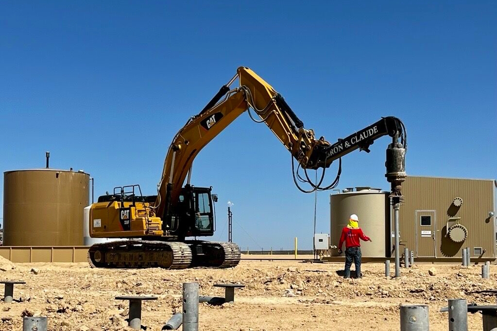
Equipment access significantly affects installation efficiency. Crews should evaluate working clearances, overhead obstructions, existing structures, utilities, slopes, soft ground conditions, and staging areas before work begins. Sites with restricted access may require compact hydraulic drive heads mounted on skid steers, mini excavators, or specialty equipment. Larger projects may utilize excavator-mounted drive systems capable of delivering higher torque outputs.
Site Layout and Pile Location Verification
Establishing Control Points
Accurate pile placement begins with reliable survey control. Reference benchmarks and control points should be established before layout activities begin. Survey crews typically transfer pile locations from approved foundation plans to field conditions using conventional surveying equipment or GPS-based systems where appropriate.
Confirming Utility Clearance
Before installation starts, underground utilities should be identified and protected according to project requirements and local regulations. Existing utility conflicts can significantly affect installation operations. Adjustments to pile locations should only occur after approval from the engineer of record or project authority.
Verifying Pile Positions
Each pile location should be clearly marked before installation equipment arrives. Inspectors frequently verify layout accuracy prior to installation because correcting location errors after installation can be difficult and costly.
Selecting Installation Equipment
Hydraulic Drive Heads
The hydraulic drive head is the primary tool used during helical pile installation. It converts hydraulic power into rotational torque capable of advancing the pile into the ground. Drive head selection depends on expected soil conditions and required installation torque. Equipment must be capable of achieving specified torque levels without operating continuously at maximum capacity.
Torque Monitoring Systems
Accurate torque measurement is essential for quality control. Modern installation systems typically use calibrated hydraulic pressure gauges, electronic monitoring systems, or integrated torque recording equipment. Since installation torque is commonly correlated with pile capacity through engineering relationships, reliable torque measurement is a critical component of the installation process.
Installation Machines
Helical piles can be installed using various carrier machines depending on project requirements. Common equipment includes excavators, skid steers, track loaders, crane-mounted systems, and purpose-built foundation installation rigs. Equipment selection should consider required torque capacity, site accessibility, vertical reach, and maneuverability.
Step-by-Step Helical Pile Installation Process
Positioning the Lead Section
Installation begins by positioning the lead section at the designated pile location. The lead section contains the helical bearing plates and serves as the first component advanced into the soil. The shaft should be aligned carefully before rotation begins. Initial alignment errors become increasingly difficult to correct as installation progresses.
Establishing Verticality
Verticality is one of the most important quality control considerations during installation. Contractors typically use spirit levels, digital inclinometers, or machine-mounted guidance systems to monitor alignment. The pile should remain as close as possible to the specified installation angle throughout the installation process. Excessive deviation may affect load transfer characteristics and structural performance.
Beginning Rotation
The drive head rotates the lead section while applying controlled downward force. The pile should advance smoothly into the ground as rotational energy engages the helices with surrounding soil. Downward crowd pressure should be sufficient to maintain engagement but not excessive. Excessive crowd force may disturb soil conditions and affect installation behavior.
Monitoring Soil Response
As the pile penetrates deeper strata, operators monitor advancement rates, torque increases, alignment, and equipment behavior. Changes in installation resistance often indicate transitions between soil layers. Experienced operators can frequently identify significant subsurface variations through torque response and penetration characteristics.
Monitoring Helical Pile Installation Torque
Why Torque Matters
Helical pile installation torque serves as one of the most important field measurements during installation. As soil resistance increases, installation torque generally increases as well. Because torque can be correlated with pile capacity using engineering methods, achieving specified installation torque is often a key project requirement.
Recording Torque Values
Torque readings should be recorded according to project specifications and manufacturer recommendations. Many projects require documentation of final installation torque, installation depth, extension quantities, and pile identification numbers. Electronic monitoring systems can provide continuous records throughout installation. Manual recording methods remain common on smaller projects.
Understanding Torque Trends
Torque should be evaluated as part of the overall installation process rather than as a single isolated value. Gradual increases often indicate progression into denser soils. Sudden spikes may suggest obstructions, cobbles, boulders, debris, or highly variable subsurface conditions. Inspectors should review torque trends alongside depth information and observed site conditions.
Installing Helical Pile Extensions
When Extensions Become Necessary
Most installations require one or more extension sections to achieve design depth or required installation torque. Once the lead section approaches ground level, installation temporarily stops so an extension can be connected.
Extension Connection Procedures
Extension sections are connected using approved mechanical connections specified by the pile manufacturer. Connection hardware should be installed according to manufacturer requirements. Inspectors typically verify proper bolt installation, alignment, and connection integrity before installation resumes.
Continuing Installation
After the extension is connected, installation proceeds using the same procedures employed during lead section advancement. Additional extensions are added as necessary until the required depth, torque, or installation criteria are achieved.
Helical Pile Refusal and Termination Criteria
What Is Helical Pile Refusal?
Helical pile refusal generally occurs when installation resistance becomes so high that additional advancement is impractical or impossible using available equipment and approved procedures. Refusal conditions may result from extremely dense soil, weathered rock, bedrock, large obstructions, or equipment torque limitations.
Distinguishing Refusal From Obstructions
Not every increase in torque represents true refusal. Localized obstructions such as buried concrete, debris, cobbles, or boulders can create temporary resistance. Contractors and inspectors should evaluate installation data carefully before determining that refusal has occurred. Engineering judgment is often necessary to distinguish between isolated obstructions and competent bearing strata.
Evaluating Termination Requirements
Termination criteria vary by project. Common acceptance criteria may include minimum installation torque, minimum embedment depth, required bearing stratum penetration, or combinations of these factors. The engineer of record ultimately determines whether installation requirements have been satisfied.
Installing Batter Helical Piles
Applications for Batter Installations
Some projects require helical piles installed at an angle rather than vertically. Batter piles are commonly used where lateral loads, overturning forces, or uplift forces govern design. Examples include retaining structures, transmission towers, boardwalks, marine structures, and utility infrastructure.
Alignment Control
Maintaining proper installation angle is critical during batter pile installation. Survey control, alignment guides, and inclinometer measurements are often used to verify compliance with project requirements. The same torque monitoring and quality control procedures used for vertical piles generally apply to batter installations.
Cut-Off Procedures After Installation
Determining Final Elevation
After installation is completed, piles are cut to the required elevation specified by project plans. Survey verification is often performed before cut-off operations begin.
Cutting the Shaft
Field crews typically use approved cutting equipment to remove excess shaft length above the design elevation. Care should be taken to avoid damaging the remaining shaft section or connection areas.
Surface Preparation
After cutting, the exposed shaft may require cleaning, grinding, or preparation before attachment of brackets, caps, or structural connections.
Installing Brackets and Pile Caps
Foundation Repair Brackets
In underpinning and foundation repair applications, specialized brackets transfer structural loads from existing foundations to installed helical piles. Proper bracket installation is essential because load transfer occurs through the bracket assembly rather than directly through the pile shaft.
New Construction Caps
For new construction applications, pile caps or structural connections are installed according to approved design details. Connection requirements vary based on structural loading, column configurations, grade beam systems, and project specifications.
Inspection Considerations
Inspectors typically verify connection dimensions, weld quality where applicable, bolt installation, and compliance with approved design documents.
Inspection and Quality Control Documentation
Installation Logs
Comprehensive installation logs provide an important record of construction activities. Typical records include pile identification numbers, installation dates, equipment information, installation depths, extension quantities, final torque values, and observations regarding subsurface conditions.
Inspector Responsibilities
Inspectors document compliance with project requirements and verify that installation procedures follow approved specifications. Observations often include alignment verification, torque monitoring procedures, component inspections, extension connections, and final termination conditions.
Final Records
Project closeout documentation may include installation logs, calibration records, survey data, inspection reports, and engineering reviews. These records become part of the permanent project documentation.
Common Helical Pile Installation Challenges
Encountering Obstructions
Buried debris, concrete remnants, cobbles, and boulders are common field challenges. When obstructions are encountered, contractors may attempt relocation, removal, or alternative installation procedures depending on project requirements and engineering approval.
Excessive Deviation
Loss of alignment can occur due to operator error, variable soil conditions, or equipment limitations. Frequent verticality checks help identify alignment issues before they become significant.
Inadequate Torque
Some installations fail to achieve required torque within anticipated depths. Potential causes include weaker-than-expected soils, inaccurate subsurface assumptions, or design changes resulting from actual field conditions. Engineering evaluation is typically required when specified torque cannot be achieved.
Equipment Limitations
Insufficient drive head capacity can prevent installations from reaching required torque levels. Proper equipment selection during project planning helps reduce these issues.
Troubleshooting Installation Problems in the Field
|
Field Condition |
Possible Cause |
Typical Evaluation Approach |
|---|---|---|
|
Sudden torque spike |
Obstruction or dense layer |
Review depth and installation behavior |
|
Low torque at design depth |
Weak soil conditions |
Evaluate capacity and termination criteria |
|
Excessive wobble |
Alignment issue or obstruction |
Verify verticality and investigate subsurface conditions |
|
Slow advancement |
Dense soils or equipment limitations |
Review torque capacity and installation data |
|
Connection difficulty |
Misalignment or component damage |
Inspect hardware and shaft condition |
Responding to Unexpected Conditions
Field conditions rarely match geotechnical predictions perfectly. Successful installation crews adapt while maintaining compliance with project requirements. Communication between contractors, inspectors, and engineers becomes especially important when unexpected subsurface conditions arise.
Maintaining Documentation
Thorough documentation often becomes the most valuable tool for resolving installation questions. Accurate records allow engineers to evaluate field conditions and make informed decisions regarding acceptance criteria and potential design modifications.
Safety Considerations During Installation
Equipment Safety
Helical pile installation involves high-torque hydraulic equipment capable of generating significant forces. Personnel should remain clear of rotating components and follow all manufacturer safety requirements.
Site Awareness
Operators and ground personnel should maintain awareness of overhead utilities, underground infrastructure, nearby structures, and changing site conditions. Safe work practices remain essential throughout all installation activities.
Training Requirements
Qualified operators and inspectors contribute significantly to project success. Training should include equipment operation, torque monitoring procedures, installation techniques, and project-specific requirements.
Successful helical pile installation requires careful coordination of planning, layout, equipment selection, alignment control, torque monitoring, extension installation, termination evaluation, and documentation. While the installation process appears straightforward on the surface, each stage affects foundation performance and project quality.
Contractors must understand how to install helical piles efficiently while maintaining alignment, achieving required torque, and documenting field conditions. Inspectors must verify compliance with project requirements and ensure installation data accurately reflects actual site conditions. When these responsibilities are executed correctly, helical piles provide a fast, reliable, and highly verifiable deep foundation solution across a wide range of construction applications.